|
|
|
No. 1. Pillar Bedding, and the flexible Remington receiver.
Pillar Bedding, and the flexable Remington receiver.
How much guard screw torque is necessary to bend a Remington M-700 receiver? See 9 photos, it is less than you
think!
| Picture #1 |  |
Remington Receiver held in stock by 2 pieces of surgical tubing. Each piece with just
1 moderately tight wrap holding the receiver in place.
| Picture #2 |  |
Lyman digital trigger pull scale showing that 4 lbs. 1 oz. was necessary to pull one end of the receiver out
of contact with the stock. Keep in mind that additional wraps of tubing would cause this number to go up.
For the sake of comparison, just One inch pound of torque on a guard screw at this point would create
a clamping force of 20 pounds pressure on the receiver.
| Picture #3 |  |
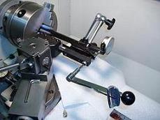
This photo illustrates the simple setup used to measure the amount of receiver movement (bending) which occurred
in the next 2 tests. The receiver tang is in the center, the indicator spindle is on the right, or top side of the receiver
tang, and positioned to record the tangs movement. A 1/4 X 28 eye bolt is screwed into the other side of the tang
where the rear guard screw would normally go. This eye bolt provides an easy means of attaching the scales used
in the next 2 tests.
| Picture #4 |  |
This
photo features the Lyman scale with 4 lbs. 2 oz. showing on the dial. I am trying to duplicate the amount of tension
placed on the receiver by one wrap of surgical tubing. And then to illustrate how even this tiny amount of pressure
on the receiver has a measurable effect.
| Picture
#5 |  |
Here is a second view of the same setup shown in the previous photo. I know that it is hard to read
the scale and the indicator but the relationship between the receiver, the indicator and the scale is easier to see in
this photo. This time, the scale shows a 4 lb. 1 oz. pull, and once again, the indicator registers a .002" movement
of the receiver.
| Picture #6 |  |
Here we see the scale showing a 50 lb. pull on the receiver while the indicator registers .028 on the dial.
What we are seeing here is that 50 lbs. pressure will bend this long action Remington M-700 receiver almost
1/32" (1/32=.031").
How much guard screw torque would be necessary to duplicate this 50 lb. pull
and thus bend the receiver a similar amount?
| Picture
#7 |  |
Here, I have changed the setup, so that I can install the rear guard screw into the receiver, turn it with
an inch pounds torque wrench, and get a reading on how much the receiver bends.
| Picture #8 |  |
Applying 4 inch pounds of torque to the rear guard screw. Yes, just 4 inch pounds of torque is all that
was necessary to bend the receiver .030" or almost exactly the same amount as with the 50 lb. pull shown in picture #6.
| Picture #9 |  |
Here,
I am trying to provide a better view of the 4 in. lbs. = .030 on the dial just as described in #8.
Next, I wanted to try 5 in. lbs. of torque, so that I could measure how much additional bending occurred. Well, I chickened
out. At 4 3/4 in. lbs. The torque shown by the pointer on the wrench stopped increasing, but the indicators dial
continued to register movement. I stopped turning the wrench when the indicator reached .038" and the wrench still
said 4 3/4 in. lbs. I never made it to 5 in. lbs. for fear of damaging the receiver.
WITH ANY NORMAL AMOUNT OF GUARD SCREW TORQUE,YOUR REMINGTON RECEIVER WILL BEND IN ORDER TO CONFORM TO THE BEDDING SURFACE
WHICH SUPPORTS IT. THIS IS BACKWARDS. THE BEDDING SURFACE IN THE STOCK MUST BE MADE TO CONFORM TO
THE RECEIVER.
This is easily done
because, Bed Heads aluminum pillars feature an installation process which places almost no bending pressure on the receiver
as they are being installed.
By the way, 5 in. lbs. of guard screw torque equals100 lbs. of clamping force,
30 in. lbs. of guard screw torque equals 600 lbs. of clamping force. 65 in. lbs. of guard screw torque equals 1300 lbs.
of clamping force.
You can verify these clamping force values at, Engineers Edge.
In the
previous photos, I am trying to illustrate how sensitive the Remington, and other, receivers are to very small amounts
of guard screw torque. The guard screw threads are very efficient in converting a small amount of rotational torque
into enough clamping force to easily overpower your actions ability to resist.
As you see, the receiver
is very easy to bend, this is why we need the receiver support provided by aluminum pillars, and a pillar installation
process which places very little pressure on the receiver while the pillars are being epoxied in place.
People who, with no other preparation, spread some epoxy into the bedding area of a stock, and then apply 10 to 20 in. lbs.
of torque to the guard screws in order to seat the barreled action into this fresh bed of epoxy, have just pulled the receiver
right back into the same stressed position which has been the problem all along.
When correctly installed,
pillars provide 2 benefits.
1. Resistance to compression by pressure from the guard screws.
2. The opportunity to achieve and maintain a stress free fit.
Both of these
features lead to better and more consistent accuracy.
Remember Ernie's Rule:
For the least amount of stress in your action.
Build
your actions foundation
while using the least amount of force!
(For information
only, do not add to cart)
Item #2001
|
|